A PSU, or power supply unit, is responsible for delivering electricity to all the components in your computer’s case. Considering its vital role, a faulty PSU can cause your system to malfunction, damage expensive parts, and at worst, blow up your computer entirely.
Whether your computer is malfunctioning and you want to see if the PSU is acting up, or if you’ve got a new PSU and want to ensure it’s healthy, you can use a handy multimeter to test your PSU. A simple multimeter capable of measuring voltage can save you a lot of trouble and money.
Why You Should Test a Power Supply Unit
The video above demonstrate that computers catching fire isn’t exclusive to cartoons. It can happen in real life too, and the culprit is often the power supply unit (PSU). This unit takes in power from the electricity outlet, converts it, and then sends it to the components in your computer.
A malfunctioning PSU might be harmless sometimes, but it’s also capable of frying all the components in your computer case. Therefore, testing a PSU by installing it in a computer to see if it works is a very expensive method. You will ultimately find out if the PSU works or not, but might end up losing thousands of dollars’ worth of computer components in the process.
On the other hand, you can use a multimeter to check the voltage on the PSU’s pins. This way, you don’t need to connect any PC components to the PSU and save yourself the risk of frying them. You can use a multimeter to find out whether the PSU is faulty, and then repair it or get a new PSU before it damages other computer parts.
Elementary Test: Does the PSU Even Turn On?
The PSU’s fan should start spinning, the moment it powers on. This is an elementary and yet essential test, because if the PSU doesn’t even turn on, then what’s the point of testing it with a multimeter?
There’s a twist to this test: a PSU won’t turn on without a motherboard. This is because the PSU has a power-on pin that connects to the motherboard. So, if you flipped the power switch on your brand new PSU and the fan didn’t spin, don’t panic. That’s how it’s supposed to be.
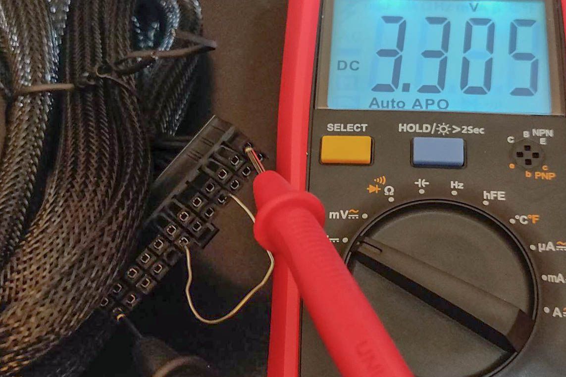
To conduct this test without risking a motherboard, you can use a paper clip to connect the power on pin to a ground pin. If your PSU’s main connector has colored wires, then the green wire goes to the power-on pin and the black ones go to ground pins. If the wires aren’t color-coded, you can use the diagram above to locate the pins on your connector. Pay attention to the clip’s position.
Wear a non-conductive safety glove before you proceed with the test. Although the electricity from a normal PSU isn’t dangerous, a faulty PSU can potentially electrocute you.
With the connector’s clip facing the ground, the power-on pin is the fourth pin from right on the bottom row. Once you’ve located the pins, here’s how you can turn on the PSU:
- Make sure the PSU is unplugged and the power switch is set to off. Off is marked with a circle (O) on the switch.
- Grab a metal paper clip and straighten it. You can also use a jumper wire, or any flexible conductor.
- Connect one end of the clip to a ground pin. These are marked with COM in the diagram.
- Connect the other end of the clip to the power-on pin.
- Plug in your PSU.
- Switch the power switch to on.
Now for the moment of truth. If the fan is starts spinning, then congratulations! You’ve passed the first test! Some PSUs have a zero rpm feature, and the fan will stop spinning after a while. So don’t worry if the fan stops spinning.
Voltage Test: Testing the PSU With a Multimeter
Now it’s time to check whether the PSU is supplying adequate power to each pin. You’ll need to measure the voltage on 13 pins that fall into three categories: 3.3V, 5V, and 12V.
Your PSU should stay on for this test, so don’t turn it off; let the power on bridge stay as it is. If you haven’t used a multimeter before, read on how to use a multimeter to get started.
- Plug the black test lead into the COM jack.
- Plug the red test lead into the VΩmA/μA jack (it may be labeled slightly differently on your multimeter).
- Turn on your multimeter and switch the dial to the DC voltage position. This is marked with a V next to a solid line with a dotted line underneath.
- Connect the black test lead to a COM pin on your PSU’s connector.
- Connect the red test lead to the PSU pin you want to test.
- Observe the voltage reading on your multimeter.
Repeat this for the remaining pins to ensure they’re providing the voltage they should. The pins have a voltage tolerance, so it’s OK if the voltage is a little bit above or below what it should be. Compare the voltage reading from your PSU with the table below:
|
Pin |
Tolerance |
Voltage Range |
|---|---|---|
|
1 |
+3.3V ± 5{2c093b5d81185d1561e39fad83afc6c9d2e12fb4cca7fd1d7fb448d4d1554397} |
+3.135 to +3.465V |
|
2 |
+3.3V ± 5{2c093b5d81185d1561e39fad83afc6c9d2e12fb4cca7fd1d7fb448d4d1554397} |
+3.135 to +3.465V |
|
4 |
+5V ± 5{2c093b5d81185d1561e39fad83afc6c9d2e12fb4cca7fd1d7fb448d4d1554397} |
+4.75 to +5.25V |
|
6 |
+5V ± 5{2c093b5d81185d1561e39fad83afc6c9d2e12fb4cca7fd1d7fb448d4d1554397} |
+4.75 to +5.25V |
|
9 |
+5V ± 5{2c093b5d81185d1561e39fad83afc6c9d2e12fb4cca7fd1d7fb448d4d1554397} |
+4.75 to +5.25V |
|
10 |
+12V ± 5{2c093b5d81185d1561e39fad83afc6c9d2e12fb4cca7fd1d7fb448d4d1554397} |
+11.40 to +12.60V |
|
11 |
+12V ± 5{2c093b5d81185d1561e39fad83afc6c9d2e12fb4cca7fd1d7fb448d4d1554397} |
+11.40 to +12.60V |
|
12 |
+3.3V ± 5{2c093b5d81185d1561e39fad83afc6c9d2e12fb4cca7fd1d7fb448d4d1554397} |
+3.135 to +3.465V |
|
13 |
+3.3V ± 5{2c093b5d81185d1561e39fad83afc6c9d2e12fb4cca7fd1d7fb448d4d1554397} |
+3.135 to +3.465V |
|
14 |
-12V ± 10{2c093b5d81185d1561e39fad83afc6c9d2e12fb4cca7fd1d7fb448d4d1554397} |
-10.80 to -13.20V |
|
21 |
+5V ± 5{2c093b5d81185d1561e39fad83afc6c9d2e12fb4cca7fd1d7fb448d4d1554397} |
+4.75 to +5.25V |
|
22 |
+5V ± 5{2c093b5d81185d1561e39fad83afc6c9d2e12fb4cca7fd1d7fb448d4d1554397} |
+4.75 to +5.25V |
|
23 |
+5V ± 5{2c093b5d81185d1561e39fad83afc6c9d2e12fb4cca7fd1d7fb448d4d1554397} |
+4.75 to +5.25V |
If the pin’s voltage falls within the voltage reading in the table above, then it’s functioning properly. Once you’ve tested all the pins, you’ll know if your PSU is healthy or not.
Alternatively, if you want to be extra cautious, you can connect a testing component like a lamp to the PSU connector and then check if the voltage reading drops or not. Each pin’s voltage should stay within its range regardless of the components attached to it.
Go Beyond Visual Inspection With a Multimeter
Although the PSU gets the least attention among computer components, it is the beating heart of your computer case. A malfunctioning PSU can cause unexpected shutdowns, impair your computer’s performance and, at worst, destroy the components.
Whether you’re troubleshooting or want to test a new PSU, you can rely on a multimeter to safely check the PSU with minimal risk. You need to bridge the power on pin to a ground pin to get the PSU started, and then check the voltage on the pins to see if they’re providing the power they should.


